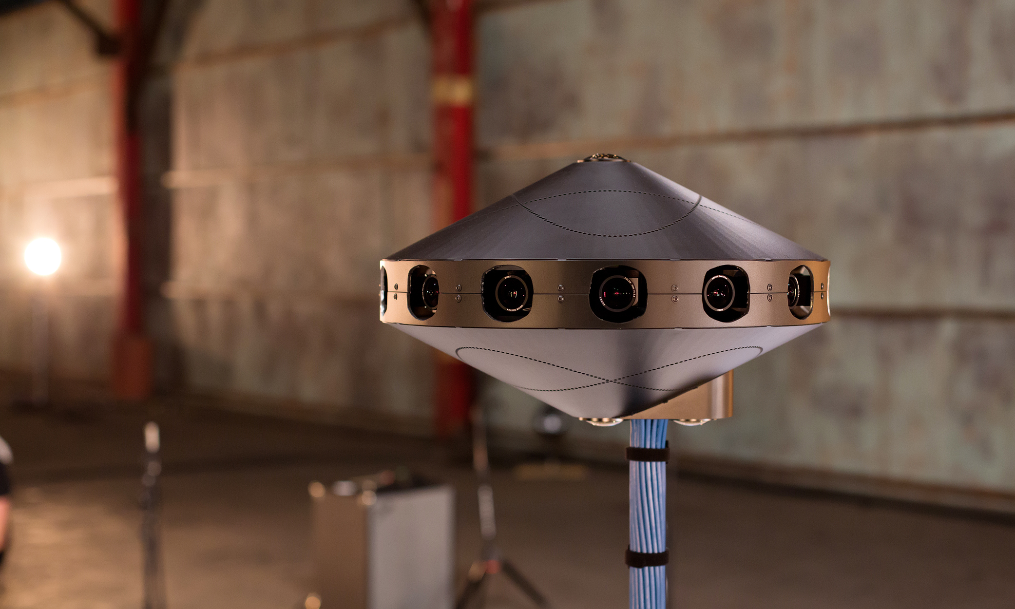
Today we officially open-sourced the specs for Surround 360, our high-quality 3D-360 hardware and software video capture system. The open source project includes the hardware camera design and software stitching code that makes end-to-end 3D-360 video capture possible in one system — from shooting to video processing.
We believe making the camera design and stitching code freely available on GitHub will accelerate the growth of the 3D-360 ecosystem — developers will be able to leverage the code, and content creators can use the camera in their productions. Anyone will be able to contribute to, build on top of, improve, or distribute the camera based on these specs.
Both the hardware design and software play a role in achieving a high-quality output. We've previously written about the hardware design of the camera and its importance in decreasing the processing time for the footage. Even though we use high-quality optics and machine-fabricated rigs, there is still enough variation between camera lenses that without software corrections, results are not viewable in stereo (you see double vision and not 3D). Our stitching software takes the images captured by the 17 cameras in Surround 360 and transforms them into a stereoscopic 360 panorama suitable for viewing in VR. This software vastly reduces the typical 3D-360 processing time while maintaining the 8K-per-eye quality we think is optimal for the best VR viewing experience. This post goes into some depth on the rendering software we created to solve this problem, covering the goals we set, the challenges we took on, and the decisions we made in developing this technology.
Challenges of rendering stereo 360 video
Rendering stereo 360 video is a hard problem for a variety of reasons:
- The amount of data involved is huge. Because we have so many cameras, and because we capture RAW, uncompressed data to preserve maximum image quality, it amounts to roughly 120 GB of data per minute of video (for 30 fps; double that for 60 fps).
- There is little room for error. For mono 360 content, some stitching errors can be tolerated, but for stereo it must be near perfect or it can cause physical discomfort.
- In order to create VR video practically, we need to be able to process all this data as fast as possible, which is often in opposition to the goal of maximizing quality.
Traditional mono stitching software won't solve these problems. It can apply relatively simple transforms to the source images, then blend them together at the edges, but this approach is not sufficient for stereo. It produces stereo inconsistencies that break perception of 3D and cause discomfort.
Methods for constructing stereo panoramas
We tried a lot of camera/software combinations as we developed our prototypes for a 3D-360 camera. Our first attempt was four pairs of cameras pointing out in a square, spaced roughly eye-distance apart. Then we tried to stitch the left and right eye images into a seamless panorama with alpha blending, which is a basic technique for mixing images together to create a smooth transition. It looked great when pointing straight out in the direction of the real cameras, but the stereo was off at the corners. Another issue with this approach is that as you rotate around, your eyes have to point in different directions to look at objects a constant distance away, which causes eyestrain.
There are more sophisticated ways to construct stereo panoramas than basic alpha blending and stitching. One approach is to take slices of the images captured by a camera that rotates around a fixed axis. This approach produces panoramas that have proper vergence and creates more consistent perception of depth than basic stitching. However, it cannot be applied to scenes where anything is moving. Going one step further, we use optical flow to simulate a rotating camera, by "view interpolation" from a small number of cameras arranged in a ring; this approach can capture scenes with motion, but optical flow is a challenging problem in computer vision research.
Using geometry to create realistic results
The Surround 360 rendering code is designed to be fast so it can practically render video while maintaining image quality, accurate perception of depth and scale, comfortable stereo viewing, and increased immersion by incorporating top and bottom cameras to provide full 360-degree x 180-degree coverage and making the tripod pole invisible.
Equirectangular projections are one technique commonly used for encoding photos and video in VR. An equirectangular projection is just a way of wrapping a sphere with a rectangular texture, like a world map. Each column of pixels in the left or right equirect image corresponds to a particular orientation of the user's head, and the pixels are what should be seen by the left and right eyes in that head orientation.
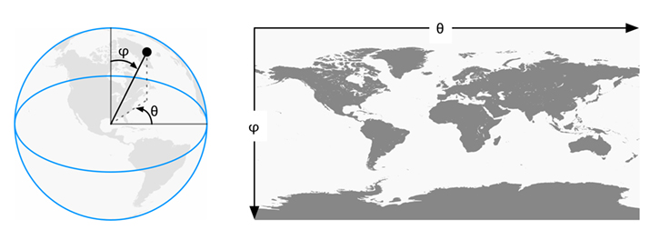
So our goal is to generate equirectangular panoramas for the left/right eyes, such that each column of pixels corresponds to a different head orientation. For a given head orientation, there are two virtual eyes spaced 6.4 cm apart (or whatever we specify), which rotate around the center of the head. From each virtual eye, we consider a ray that goes out in the direction of the nose, and we want to know what color the light from the real world is along that ray. That is the color we should use for the corresponding pixel in the equirectangular image.
Now imagine all this is happening inside the camera (from a 2D top-down perspective); the center of the head is the center of the camera. The ray we constructed through each pixel starts at a virtual eye and eventually exits the circle of cameras. If that ray passed right through a real camera, we would know what color it should be from some pixel in the camera's image. But usually the ray exits the circle where there is no real camera. In this case, we use view interpolation to generate a virtual camera in between the real cameras, and get the ray color from a pixel in the interpolated view.
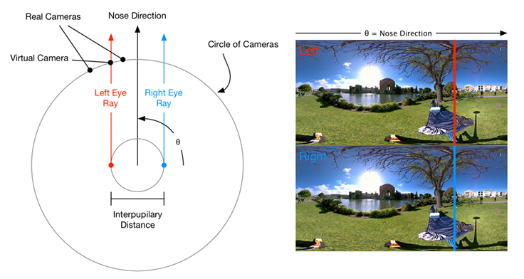
The description above is a model of how the stereo equirectangular images that we render correspond to the color of light along rays in the real world, which explains why it feels realistic (although it is a rough approximation).
Rendering pipeline
In practice, we implement the above model in a pipeline of image processing stages. There are many steps in the pipeline, but it is mostly automatic, so the time to render is still considerably less than manual stitching.
First, cameras output RAW bayer pattern images. The Image Signal Processor (ISP) part of the Surround 360 rendering code converts the RAW sensor data to a standard RGB format .png image, applying gamma and color correction. Then, the rendering system reads the camera images and builds equirectangular projections from each. The equirectangular projection covers a whole sphere with a rectangular texture. Each camera captures only a portion of the full sphere, but this can still be represented on an equirectangular projection. We found it convenient to use this projection throughout all subsequent stages of the pipeline.
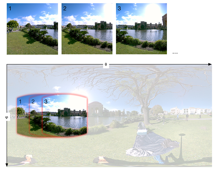
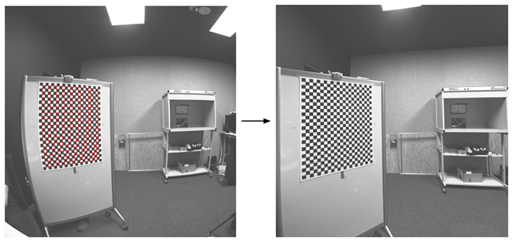
While projecting the original image to equirectangular, we apply corrections for lens distortion. We calibrate models for lens distortion by taking many pictures of checkerboards, which is a common approach in computer vision.
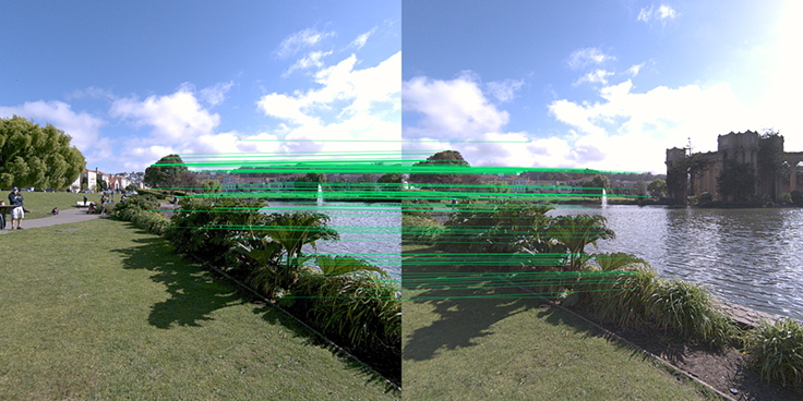
We also correct for rotational or translational misalignment of the camera/lens/mounting system, which would cause vertical parallax (which causes double vision and breaks 3D). We do this by finding matching key points in images from all adjacent cameras, and optimizing a perspective transform for each camera that rectifies all the cameras jointly, to minimize vertical parallax (the vertical difference between where an object appears in the left eye's image, and in the right eye's image).
All the cameras are projected to equirectangular in such a way that objects at a distance of infinity from the camera are aligned with zero displacement, while any difference in object position between different cameras in the equirectangular projection corresponds to parallax from being closer than infinity. This helps optical flow, because it typically starts with an initial guess of 0 flow, which is the right answer for things that are far away.
Overlapping regions of the images from neighboring cameras are extracted, and optical flow is computed between them.
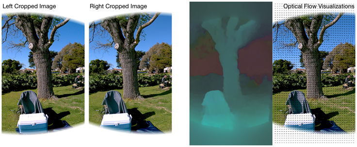
Optical flow is used to do view interpolation, so we can get the rays we need from virtual cameras.
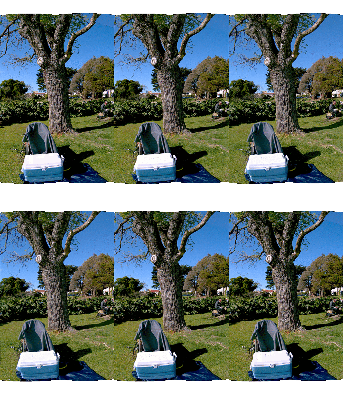
So far, we have described how to render the side stereo parts of the panorama. We also incorporate top and bottom cameras to make it more immersive by providing full 360-degree x 180-degree coverage. The side cameras are wide-angle lenses with roughly 90-degree horizontal and vertical FOV (which decreases to 77 degrees after correcting for barrel distortion). So that covers a 77-degree strip at the horizon, out of the full 180-degree vertical range. We have cameras with different 180-degree fisheye lenses on the top and bottom to fill in those holes with mono. It actually has to be mono at the very top and bottom because there is no way to bake correct stereo for all head orientations into a left/right equirectangular image pair, so we make it gradually transition from stereo at the horizon to mono at the poles. With different lenses, we could increase the stereo range at the horizon, but that is a trade-off with resolution/pixel density.
To seamlessly stitch the top camera with the side camera left/right images in a way that produces comfortable stereo, we use optical flow to match the top image to the side panoramas. Then the top image is warped according to the flow and alpha-blended (with deghosting) to composite the images.
There are two cameras on the bottom, so we can automatically remove the tripod pole. The primary bottom camera is in the center of the rig, symmetric with the top camera. The problem is, a big chunk of its image is blocked by the tripod pole. The secondary camera is on the other side of the pole, so it sees the part of the scene that is blocked by the pole in the primary camera's image. We build a synthetic image that would have been seen by the primary bottom camera but with the pole removed. This is done by specifying a mask of the pole in both images, then using optical flow to warp the secondary image onto the primary image, and mixing the two such that the primary pixels are used unless they are in the pole mask, and otherwise the warped secondary pixels are used. After the two bottom images are fused to remove the pole, the result is stitched to the side left/right eye panoramas similar to the top camera.

All this happens in multiple threads to take advantage of multi-CPU systems. For example, optical flow can be computed between all image pairs simultaneously. Beside that, each step of the processing pipeline is scheduled according to its dependencies on other steps, to keep all the CPUs busy for as much of the rendering time as possible.
Just the beginning
This rendering pipeline produces high-resolution stereo 3D-360 panoramas that occupy the full 360-degree x 180-degree sphere for a highly immersive experience. We have taken great care to preserve image quality at every step of the pipeline, to optimize for speed, and to produce the most accurate approximation to reality that is practical with off-the-shelf hardware. We are very excited to contribute all the hardware designs and software as open source and to continue to iterate on the design, the code, and the whole 360 pipeline in the future. We hope this will inspire others to build their own stereo 360 rigs and, most of all, to capture truly immersive experiences. Please let us know what you think and what you contribute back to the community.
