Over the past few years, we’ve been working to upgrade our data centers to run at 100 gigabits per second. To do so, we needed to deploy 100G optical connections to connect the switch fabric at higher data rates and allow for future upgradability — all while keeping power consumption low and increasing efficiency. We created a 100G single-mode optical transceiver solution, and we’re sharing it through the Open Compute Project. A detailed specification, CWDM4-OCP, was contributed to OCP, and more information on the CWDM4-OCP design guide can be found here.
In this post, we’ll provide a behind-the-scenes look at the optical transceiver solution in our data centers.
Optical interconnects inside Facebook data centers
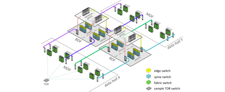
All of the compute and storage elements inside our data center are networked together using a switching architecture we call data center fabric. The switches in this network are all connected using optical signals carried over glass fiber cables. The diagram below (Figure 1) shows the physical layout of a typical Facebook data center built using our fabric architecture.

The switch network consists of structured cabling with lengths of trunk fibers (shown as colored pipes) that terminate at patch panels. The patch panels act as rack connection points, from which jumper cables (not shown) connect the patch panels to the switches. At each of these endpoints, an optical transceiver converts electrical signals to optical to be transmitted over optical fiber, and receives the optical signal from the other end to convert it back into an electrical signal. At data rates of 10 Gb/s or 40 Gb/s, we could cover most of the distances in our data centers using multi-mode fiber. The 40G optical transceivers consisted of up to four channels, each operating at 10 Gb/s and carried over a separate multi-mode fiber in a parallel configuration.
It is a big practical and financial challenge when fiber needs to be changed at each generation of interconnect technology. It takes a significant amount of time and money to re-cable tens of thousands of kilometers of fiber in a data center. As the data rate increases, dispersion (modal and chromatic) limits the length over which optical signals can be transported. For example, at 40 Gb/s the data center was cabled with OM3 multi-mode fiber. To reach 100 meters at 100 Gb/s using standard optical transceivers would require re-cabling with OM4 multi-mode fiber. That is workable inside many smaller data centers, but it does not allow any flexibility for longer link lengths or for a data rate evolution beyond 100 Gb/s. Ideally, the fiber plant should remain installed for the whole life of the data center and support many technology innovation cycles.
For these reasons, there was strong motivation to move to deploying single-mode fiber in data centers that would allow future-proofing of reach through many data rate evolution cycles. Single-mode fiber eliminates modal dispersion problems and has been used for decades in the telecommunications industry to support longer reaches at higher data rates. The only disadvantages were that these single-mode optical transceivers have historically consumed more power and been much more expensive than multi-mode transceivers. Facebook tried to tackle these two challenges by optimizing the transceiver technology to the actual needs of our data centers.
To determine the best solution for 100G optical connections, we did an analysis of the total link cost for several different scenarios. The scenarios included parallel multi-mode fiber, parallel single-mode fiber, and duplex single-mode fiber. The model included the whole link, which is made up of the cabled strands of fiber, patch panels to connect fiber throughout the data center, and the optical transceivers at each end. The analysis showed that the cost saving in using less fiber and patch panels could more than offset the increased cost of the single-mode optical transceivers. We saw an opportunity to reduce that cost even further by optimizing the specification to fit data center requirements and benefit from innovation in new technologies.
100G single-mode optical transceivers
To understand how these efficiency gains were achieved, it is useful to understand the many aspects that make producing single-mode optical transceivers harder. First, single-mode fiber has a much smaller core diameter (~9 micron) compared with multi-mode fiber (~50 micron), which means that all components must be positioned and aligned to sub-micron tolerances using high-end assembly equipment. Second, single-mode transceivers are typically produced in lower volumes for the telecommunications market, which has a demanding set of performance requirements:
- Link lengths of 10 km and over.
- Multiple wavelengths on narrow wavelength grids (DWDM and LAN-WDM) that require active cooling.
- Support for a wide range of case temperature ranges (0-70 deg C or more).
- Service lifetimes, sometimes in excess of 20 years, that require hermetic packaging to withstand potential prolonged harsh environmental conditions.
Looking at these factors, we identified a specification that would meet the requirements of the data center application by reducing the reach and link budget, decreasing the temperature range, and setting more realistic expectations for service life while maintaining high quality and reliability.
Competition between suppliers had encouraged many novel technology approaches and manufacturing improvements. As suppliers looked for ways to differentiate, the 100G optical transceiver market became fragmented with many different standards and yet more multisource agreements (MSAs). Of the various options, we chose the 100G-CWDM4 MSA and modified it to meet the particular requirements of the data center environment.
The starting point for this specification is the CWDM4 MSA, a standard that was agreed upon in 2014 by several optical transceiver suppliers. It uses a wider wavelength grid (CWDM = 20 nm spacing) and, for many of the different technology approaches, does not require a cooler inside the module to keep the laser wavelength stable.
As shown in Figure 1 above, the switches are connected together using a network of optical fibers and patch panels. Optical transceivers at each end of the link are used to interface to the electrical switches. The simplicity of the optical link is demonstrated in Figure 2. Its relative short distance allowed the reach to be reduced from 2 kilometers to 500 meters, based on a reduced link loss of 3.5 dB rather than 5 dB.

Most data centers operate under a highly predictable thermal environment, with a very well-controlled air-inlet temperature to the switching equipment. When the air-inlet temperature is well controlled, so too is the thermal environment inside the switch. This means that we could relax the specification of the operating case temperature on the optical transceiver from 0-70 deg C to 15-55 deg C. These specification relaxations are summarized in Table 1 below. This relaxed specification ensures that optical transceivers will interoperate with the standard MSA version of the specification over distances shorter than 500 meters.

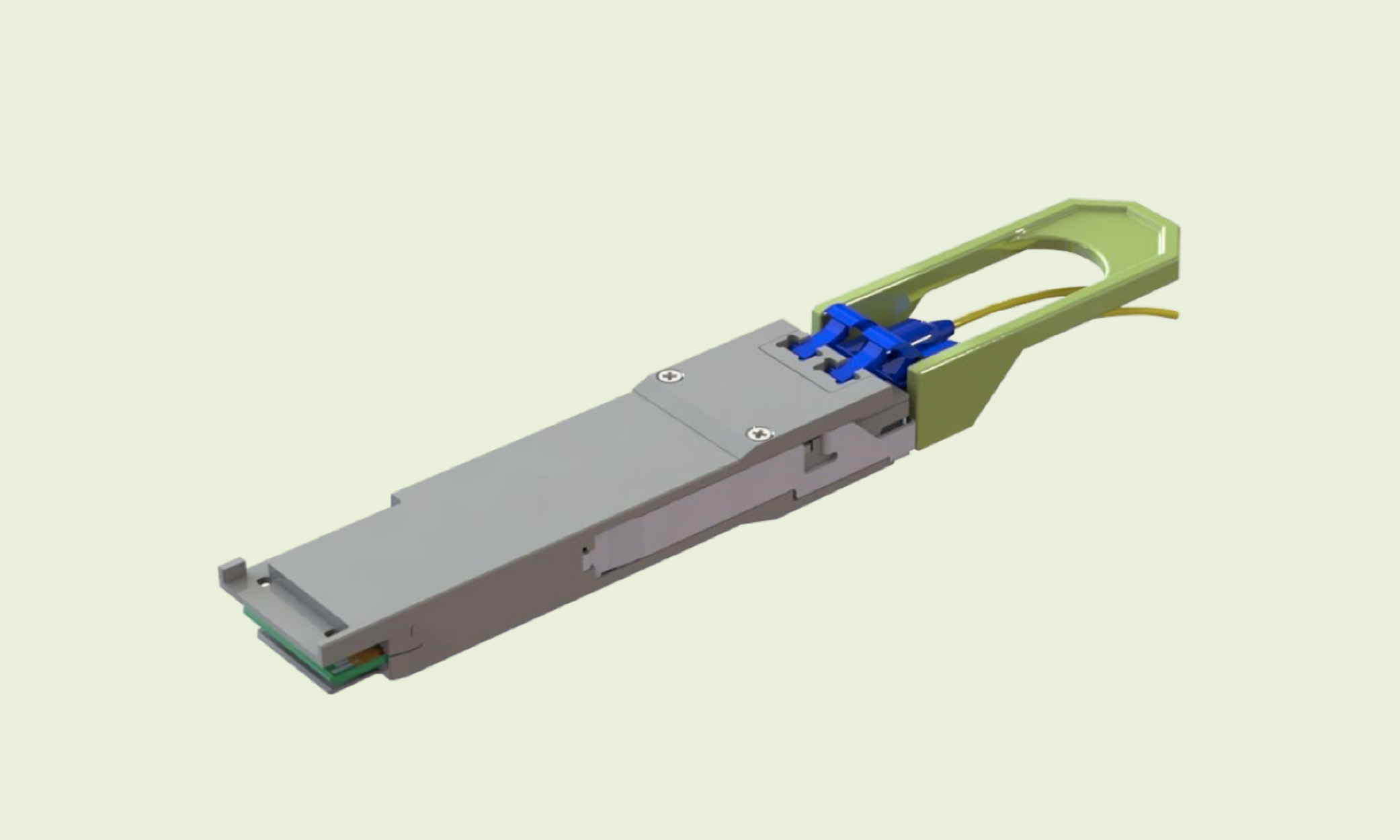
We’ve already started the deployment of this solution in several data centers, and the CWDM-OCP version of the optical transceivers is already commercially available. The OCP version can be distinguished from other versions by the “OCP green”-colored pull tab, as shown in Figure 3.

Achieving scale on schedule
When we made our decision to deploy 100G, there were no CWDM4 optical transceivers in production — making this project challenging. As an early adopter of new technology, we had to work hard to ensure successful deployment, and we learned some lessons along the way.
Using new products brings with it many risks, in terms of technology as well as production ramp and deployment. Even though many of the technology building blocks used inside 100G CWDM4 transceivers had been used at 40 Gb/s, there were still many challenges to overcome to increase them to the higher data rate. To mitigate these risks, we used several strategies.
One of these strategies was to reduce the technology risks by considering many technology platforms. These included those already being used for long-reach 100G applications, such as electro-absorption modulated lasers (EMLs), as well as taking technology used at 40G and stretching it to 100G. For example, directly modulated lasers (DMLs) were being developed with a rate increase from 10 Gb/s to 25 Gb/s per lane. The CWDM wavelength grid allowed the use of DMLs without thermoelectric coolers, which reduced power consumption. Additionally, the reduced temperature range helped new technologies, such as silicon photonics, compete.
Another strategy we used to mitigate deployment risks was to conduct rigorous inspections and testing. In addition to the testing done at suppliers, we tested optical, electrical, and thermal parameters at the module level and the equipment level with our own switching gear. To be sure that equipment would perform reliably once installed, we tested at the system level in the data center environment. By stressing the system at temperature, we were able to accelerate failure modes and screen out critical problems early. We encountered a whole spectrum of technical problems, but testing early allowed us to screen out all kinds of issues that would have held up deployment. From simple errors of EEPROM coding to complex laser issues, we were able to correct problems before equipment saw live traffic, and we stayed on schedule.
Facebook deploys network infrastructure on a large scale. Deploying a whole data center in a few months is challenging even with mature technology. Trying to do it with products that were early in production challenged the traditional approach to capacity ramp. Most optical transceiver products ramp up slowly, making a few hundred modules over a period of time, while developing optimizations to improve yield and increase manufacturing capacity before the big volume hits. Data centers deploy on a much faster schedule — about two years from breaking ground on a site to running live traffic. To ramp to volume capacity fast, we worked with a mix of suppliers that included large, established players with traditional manufacturing techniques as well as newcomers to challenge incumbents with highly automated techniques.
Making sure that a production facility is running smoothly and at full capacity means making sure that the systems and process controls are in place. We focused on manufacturing process control, supply chain contingencies, process qualification, and yield. We worked with our suppliers to provide as much information as possible on demand forecast, and we relaxed the CWDM4 specifications to improve yield from the beginning so we could achieve our demanding schedule.
Conclusions
As an early adopter of 100G single-mode optical transceivers, we worked to mitigate risks and ensure the reliable deployment of cutting-edge technology on schedule. We have established an ecosystem of equipment that works at 100 Gb/s and defined a relaxed optical transceiver specification, CWDM4-OCP, that is optimized for data centers. We are sharing this experience with the data center community through forums such as the Open Compute Project to drive wider adoption.


