
- Disaggregated Schedule Fabric (DSF) is Meta’s next-generation network fabric technology for AI training networks that addresses the challenges of existing Clos-based networks.
- We’re sharing the challenges and innovations surrounding DSF and discussing future directions, including the creation of mega clusters through DSF and non-DSF region interconnectivity, as well as the exploration of alternative switching technologies.
Disaggregated Schedule Fabric (DSF) is Meta’s next-generation network fabric. The GenAI boom has created a surge in demand for high-performance, low-latency, and lossless AI networks to support training AI models at a large scale. DSF helps us build scalable AI networks by breaking the physical limit of the traditional monolithic chassis-switch architecture. By disaggregating line cards and fabric cards into distinct, interconnected hardware devices, the DSF network creates a distributed system that offers scalability and performance for AI networks.
DSF is a VOQ-based system powered by the open OCP-SAI standard and FBOSS with a modular architecture designed to optimize load balancing and congestion control, ensuring high performance for both intra and inter-cluster traffic.
With DSF we’ve already been able to build increasingly larger clusters that interconnect thousands of GPUs in a data center region.
Background: Our Challenges With Traditional IP Fabric
While running training jobs over traditional IP fabric, we faced several challenges. These problems were specific to training applications that use remote direct memory access (RDMA) technology, which uses UDP protocol to exchange data.
We encountered these three types of problems:
- Elephant flows: AI workloads tend to have long-duration, heavy-traffic flows that have the potential to congest the fabric links they hash onto and create head-of-the-line blocking.
- Low entropy: Depending on the number of GPUs involved in the collective operations, the number of IP flows could be lower, which results in inefficient hashing and, possibly, in congestion, despite the availability of adequate capacity in the fabric.
- Suboptimal fabric utilization: We have observed that, as a combined effect, there is a large skew in the bandwidth utilization of fabric links. This is important data because it impacts how much we should overprovision the fabric to support good pacing and maintain steady performance in the event of failures.
We tried several solutions to handle these issues, but each presented challenges. For example, we created Border Gateway Protocol (BGP) policies such that when traffic is received from accelerators via leaf switches, it is pinned to a specific uplink, depending on its destination. This alleviated the problem of low entropy in steady state but didn’t handle failure scenarios where the fallback was equal-cost multipath (ECMP) routing.
We also tried load-aware ECMP schemes that could handle fat flows and low entropy, but they were difficult to tune and created out-of-order packets, which is detrimental to RDMA communication.
We also created a traffic-engineering solution that would pre-compute the flow pattern depending on the models used and configure the leaf switches before the job starts. This could handle fat flows and low entropy but grew too complex as network size increased. And due to its centralized nature, this set-up was slow to react to failures.
A Primer on Disaggregated Scheduled Fabric
The idea behind DSF stems from the aforementioned characteristics of AI training workloads, particularly their tendency to generate “elephant flows” — extraordinarily large, continuous data streams — and “low entropy” traffic patterns that exhibit limited variation in flow and result in hash collisions and sub-optimal load distribution across network paths. The fundamental innovation of DSF lies in its two-domain architecture, which separates the network into the Ethernet domain, where servers and traditional networking protocols operate, and the “fabric” domain, where packets will be broken into cells, sprayed across the fabric, and subsequently reassembled at the hardware before being delivered back to the Ethernet domain.
DSF is built on two components: interface nodes (INs), also referred to as rack disaggregated switches (RDSWs), and fabric nodes (FNs), known as fabric disaggregated switches (FDSWs). INs serve as the network-facing components that handle external connectivity and routing functions, and that interface with the broader data center infrastructure. FNs operate as internal switching elements dedicated to high-speed traffic distribution across the fabric without requiring Layer 3 routing capabilities.
To the external network infrastructure, this distributed collection of INs and FNs appears as a single, unified switch, with the total number of external ports equivalent to the aggregate of all external ports across all INs, effectively creating a virtual chassis switch that scales far beyond the physical limitations of traditional designs. The control plane that orchestrates this distributed system is built upon Meta’s FBOSS, an open-source network operating system that supports the multi-ASIC control requirements of disaggregated fabrics. Its communication with FBOSS State DataBase (FSBD) enables real-time state synchronization across nodes.
DSF achieves traffic management by packet spraying and a credit-based, congestion control algorithm. Unlike conventional Ethernet fabrics that rely on hash-based approaches, DSF utilizes packet spraying that distributes traffic across all available paths through the fabric. Such a feature is enabled by the hardware’s ability to reassemble packet cells at the interface nodes within the fabric domain while ensuring in-order delivery to end hosts.
This packet-spraying capability is orchestrated through a credit-based allocation scheme where ingress INs dynamically request credit tokens from egress INs, allowing the system to make real-time decisions based on current path availability, congestion levels, and bandwidth utilization. Virtual output queuing (VOQ) helps with ensuring lossless delivery throughout this process, directing incoming packets to virtual output queues targeting specific destination ports and service classes, with each virtual output queue being scheduled independently for transmission, providing fine-grained traffic management that can accommodate the requirements of AI workloads and communication patterns.
This approach allows DSF to achieve near-optimal load balancing across all available network paths, effectively utilizing the full bandwidth capacity of the fabric. It provides the flexibility to handle mixed traffic patterns and adapt to dynamic network conditions without requiring manual reconfiguration or traffic engineering.
DSF Fabric for GenAI Applications
DSF Fabric (GenAI)
Using the DSF technology, we built a massive cluster that interconnects thousands of GPUs within a data center region. Figure 1 illustrates the network topology of a single AI zone that is a building block for the larger cluster.
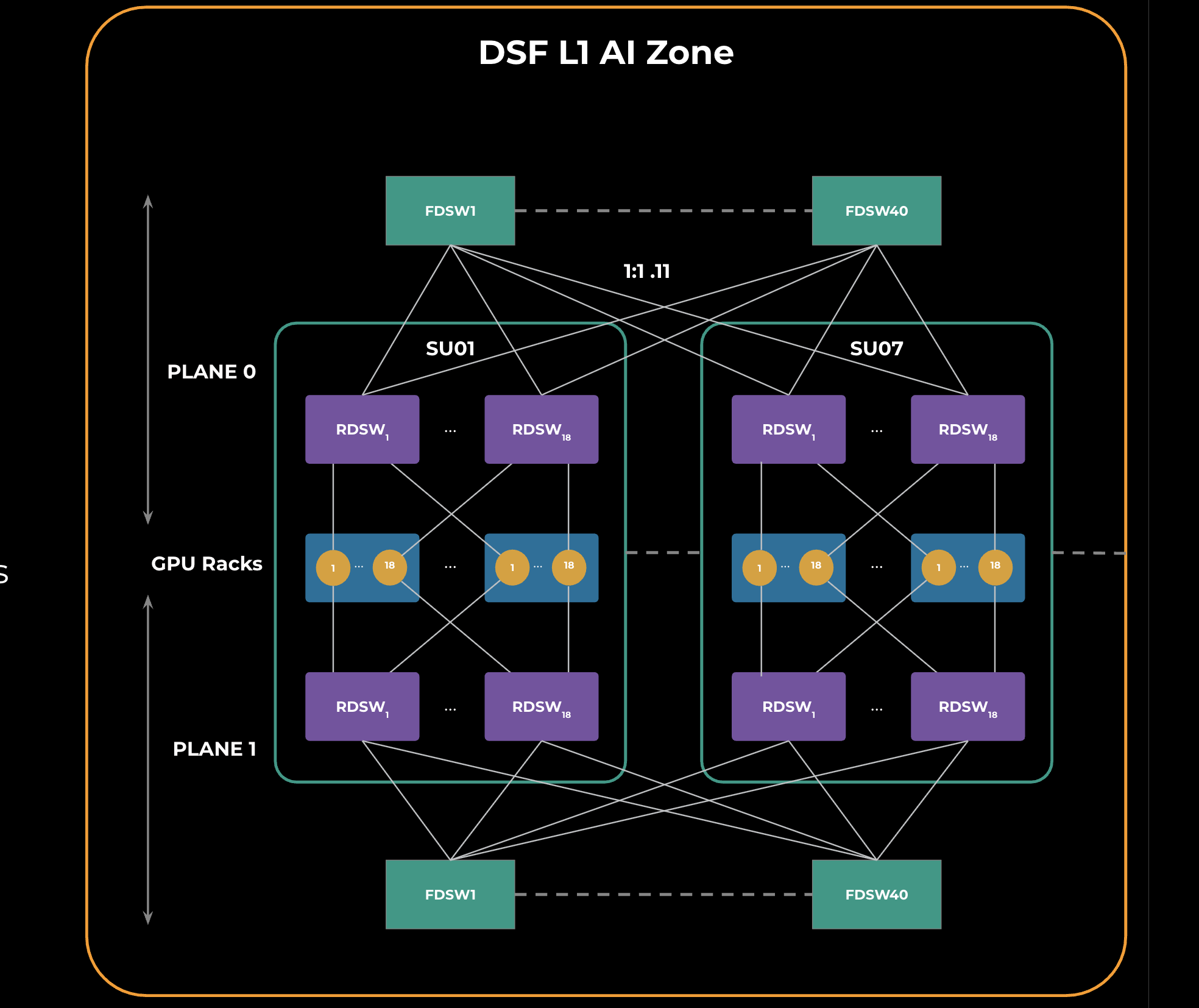
An AI zone contains multiple scaling units, shown in Figure 1 as “SUx.” A scaling unit is a grouping of GPU racks connected to RDSWs within the scaling unit. All the RDSWs within the AI zone are connected via a common layer of FDSWs. RDSWs are powered by deep-buffer Jerico3-AI chips, while FDSWs use Ramon3 chips. FBOSS is the network operating system for all the roles in this topology. We are using 2x400G FR4 optics between RDSW-FDSW connections.
The GPU to RDSW connections are rail optimized, which benefits hierarchical collectives like allreduce and allgather, both of which are latency sensitive.
To support high GPU scale in a single AI zone, two network planes that are identical to each other are created. This is called a DSF L1 zone and is a building block for larger GenAI clusters, as we will see in the next section.
DSF Dual-Stage Fabric (GenAI)
As depicted in Figure 2 (below) we interconnected 4x DSF L1 zones through a second stage of spine DSF switches (SDSWs). SDSWs use the same hardware as FDSWs and aggregate DSF L1 zones, enabling them to act as a single DSF fabric. This is a non-blocking topology providing an interconnected GPU scale of 18K x 800G GPUs.
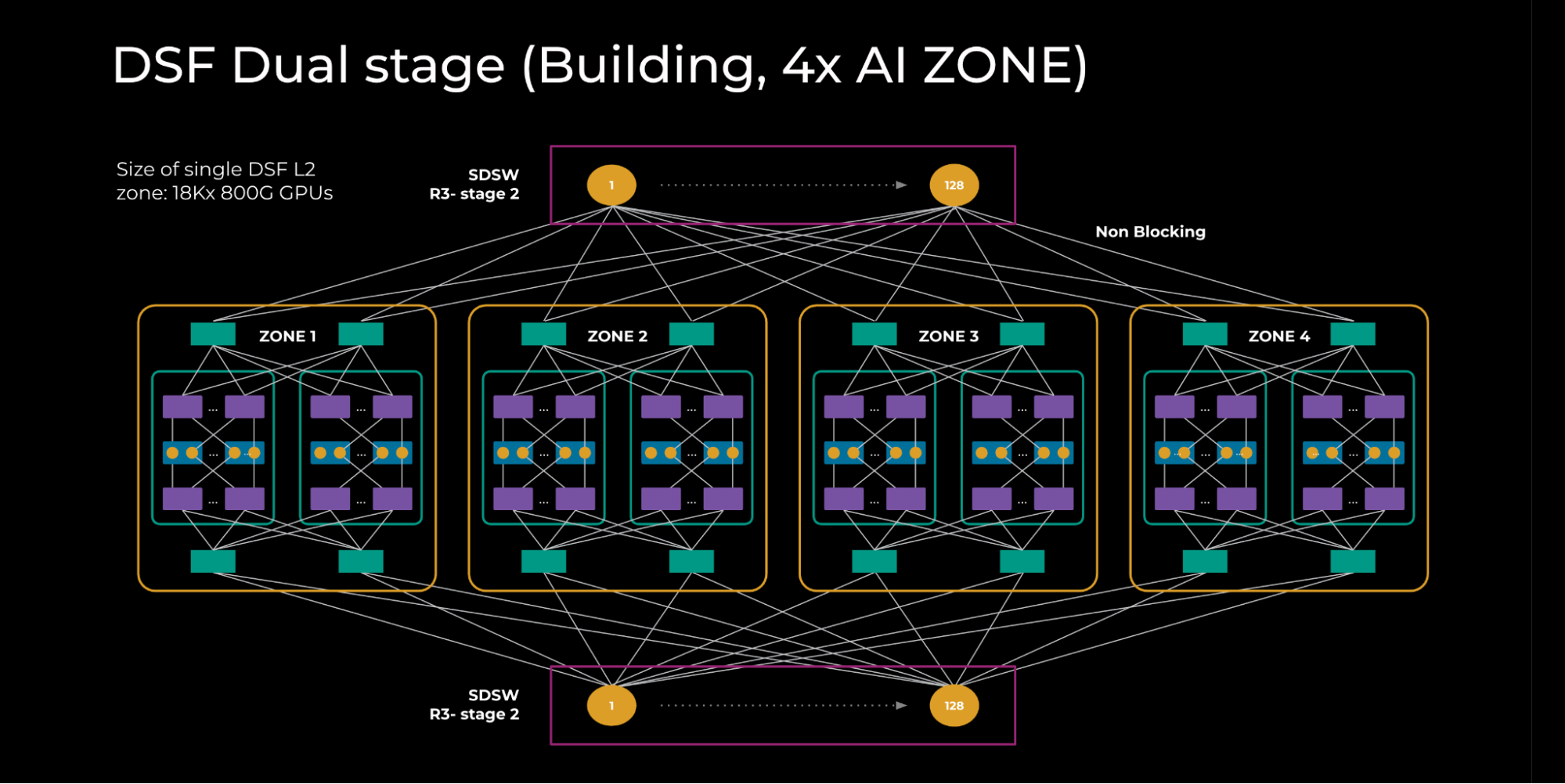
All RDSWs in this topology maintain fully meshed FDSB sessions to exchange information such as IPv6 neighbor states. There is also an innovative feature — input-balanced mode — enabled over this fabric to smartly balance the reachability info across the layers such that, in case of failures, congestion is avoided over the fabric and spine layer. This feature will be explained in a separate section below. We call this topology the DSF L2 zone.
DSF Region (GenAI)
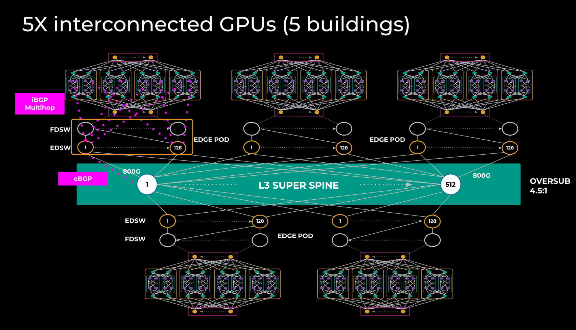
To achieve a larger interconnected GPU scale, we connected 5x DSF L2 zones via the L3 super-spine layer. (See Figure 3 below.) We did this by using a special edge point of delivery (PoD) in each of the buildings. Edge PoDs consist of 40 FDSWs and 128 edge DSF switches (EDSWs). From a hardware point of view, EDSW is the same as RDSW but differs in its function of providing connectivity to the L3 super spine.
Each EDSW connects to four superspine devices using 4x800G links provisioning a total of 2k x800G ports per edge PoD.
The way training models are sharded we don’t expect a lot of traffic transiting the L3 super-spine layer; hence, an oversubscription of 4.5:1 is sufficient.
This creates an L3 interconnect, which means we need to exchange the routing information. We created iBGP sessions with EDSW and all RDSWs within the building, with BGP add-path enabled such that RDSWs learn aggregates via all 2k next-hops.
eBGP is used between EDSW and the L3 super spine, and only aggregates are exchanged over BGP peerings.
Given that L3 spine is used, some of the problems, including entropy and fat flow, tend to reappear; however, at this network tier where there’s much less traffic, those problems are less profound.
Input Balanced Mode
Input Balanced Mode is a critical feature that supports balanced traffic throughout the network in the face of remote link failures. The feature avoids severe congestion on the fabric and spine layer of the DSF network.
Mechanism
The purpose of Input Balanced Mode is to ensure any DSF devices have equal or less input BW compared to output BW. No oversubscription should occur in the network, even in the case of remote link failure. Devices experiencing link failure will propagate the reduced reachability information across the cluster, notifying other devices to send proportionally less traffic to the affected device.
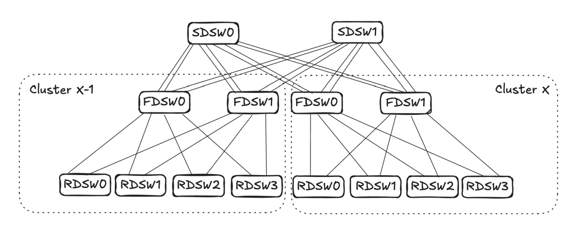
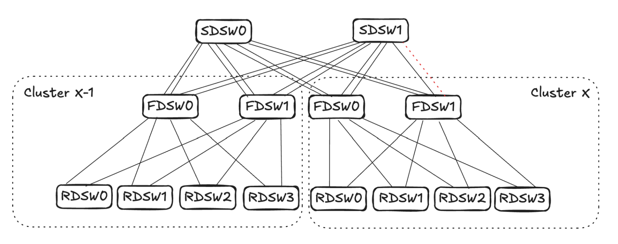
Note: For clarity, in Figure 4, FDSW/SDSW are simplified to only show one virtual device. The above graph will be used to illustrate two different link failures and mechanisms.
RDSW<->FDSW Link Failure
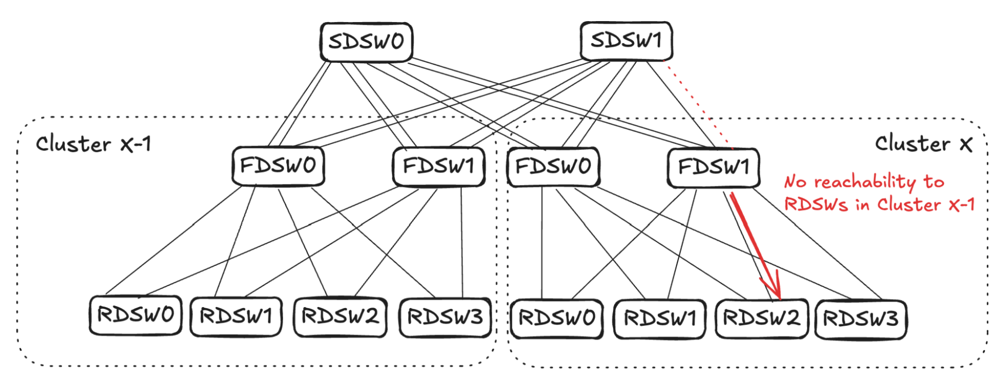
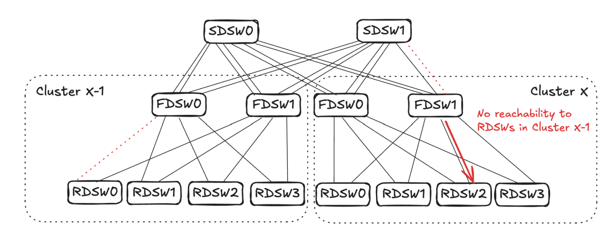
In the case of RDSW<->FDSW link failure, RDSW will lose connectivity to the FDSW, hence losing both input and output capacity on the link. FDSW also loses connectivity to the RDSW and then stops advertising the connectivity. In Figure 5 (below) FDSW1 in Cluster X loses connection to RDSW3, hence it stops advertising reachability to SDSW0 and SDSW1.
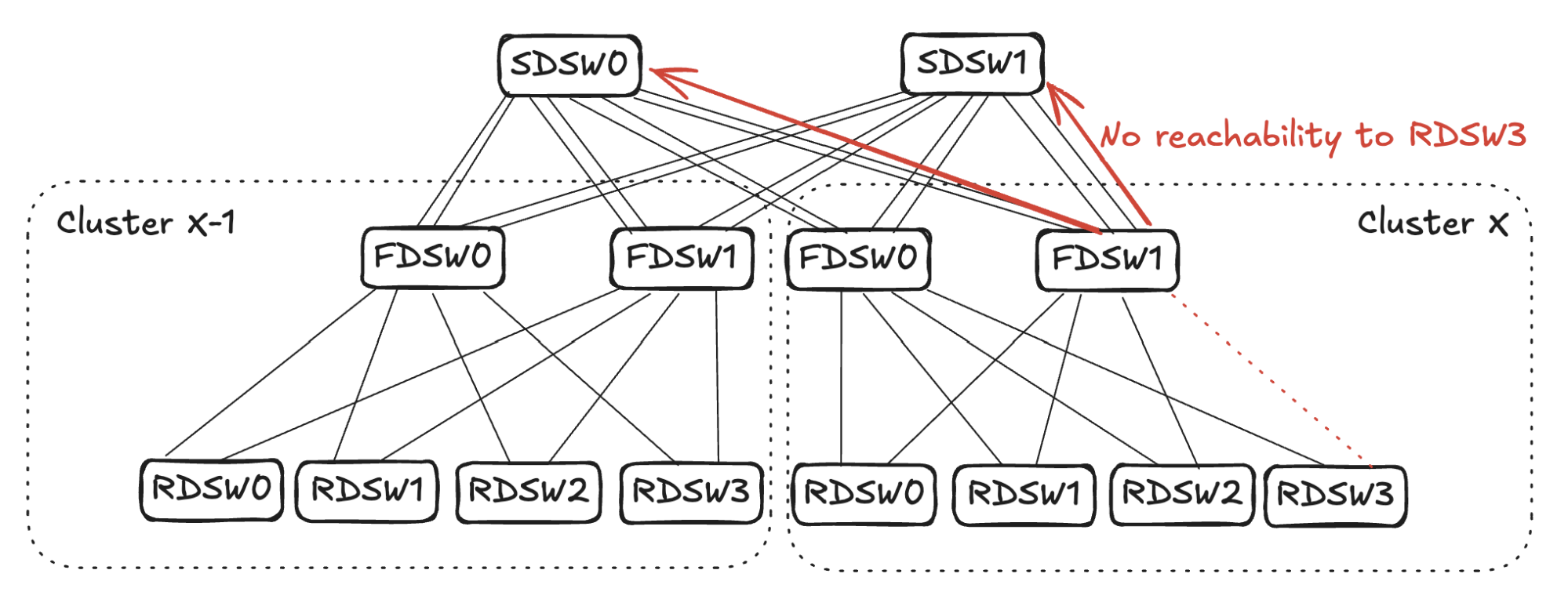
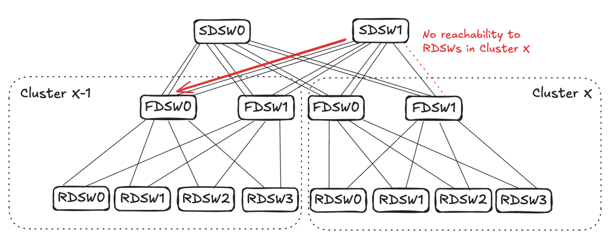
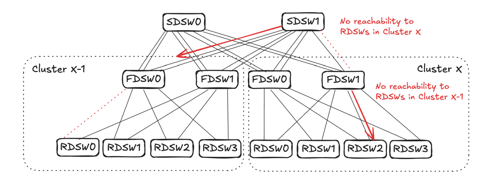
From SDSW0’s perspective, it receives no reachability to RDSW3 from FDSW1 in Cluster X, but still has reachability to RDSW3 through FDSW0. (See Figure 6.) Toward destination RDSW3 in Cluster X, the input capacity of 4 (FDSW0 and FDSW1 from Cluster X-1) is greater than the output capacity of 2 (FDSW0 in Cluster X). To avoid oversubscription, SDSW0 will pick two input links and stop advertising reachability toward RDSW3 in Cluster X. The same sequence will also take place in SDSW1.
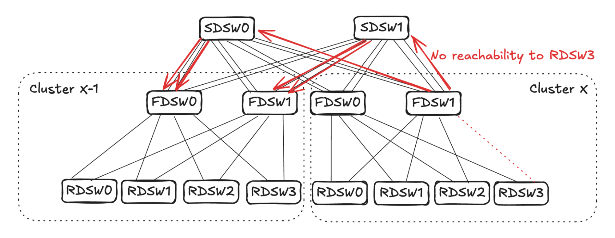
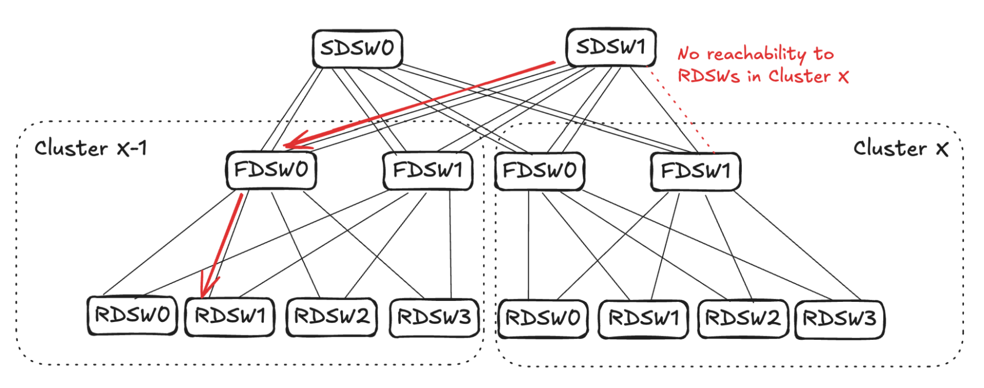
The link selection for balanced input mode should be randomized. As shown in Figure 7 (below), for simplicity’s sake, assume SDSW0 stops advertising reachability to FDSW0, and SDSW1 stops advertising reachability to FDSW1. Both FDSW0 and FDSW1 have an input capacity of 4 but an output capacity of 2, hence randomly selecting two links on each device to not advertise reachability.
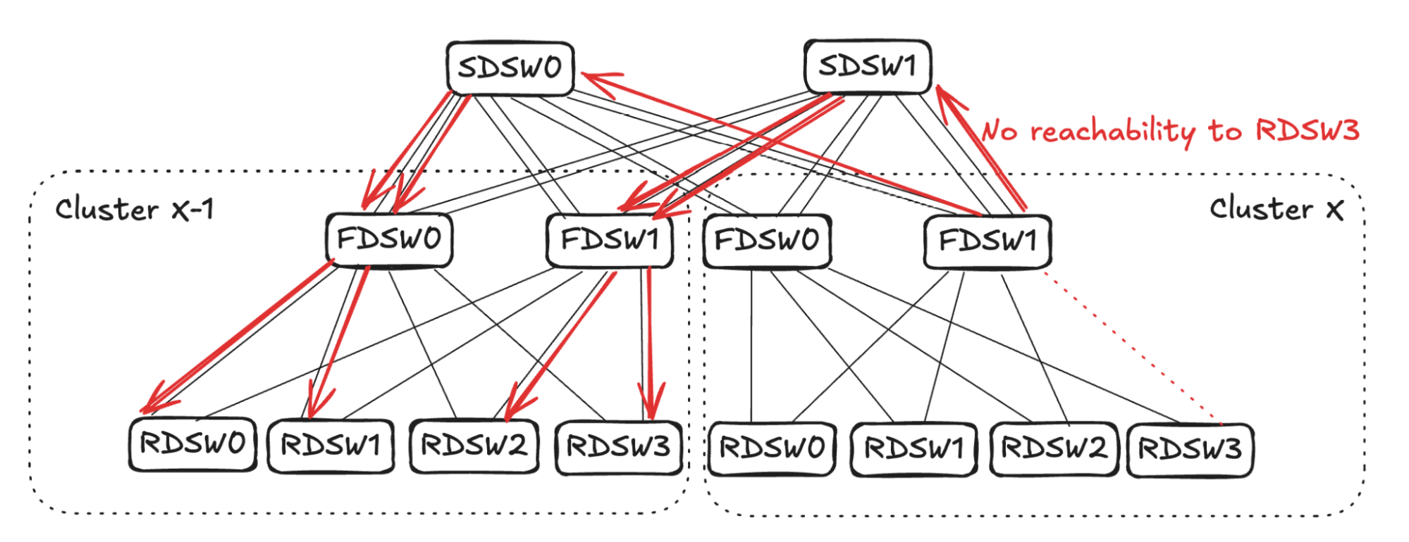
Assume FDSW0 randomly selects links to RDSW0 and RDSW1, while FDSW1 randomly selects links to RDSW2 and RDSW3. This completes the propagation of link failure, resulting in RDSWs in Cluster X-1 having 50% capacity to forward traffic toward RDSW3 in Cluster X.
FDSW<->SDSW Link Failure
Upon FDSW<->SDSW link failure, there are two directions to propagate the reduced capacity: 1) on FDSW, reduce input capacity from RDSW, and 2) on SDSW, reduce input capacity from FDSWs in other clusters. (See Figure 8)
FDSW Propagation
Consider the traffic egressing out of Cluster X thru FDSW1 (see Figure 9): From FDSW1’s perspective, input capacity is 4 (from RDSW0-RDSW3) while output capacity is reduced to 3 due to link failure.
To balance input capacity, FDSW1 will randomly pick one FDSW<->RDSW link to stop advertising reachability to ALL destinations outside of the cluster.
Assume Cluster X FDSW1 randomly picks the link to RDSW2. It will stop advertising reachability to all RDSWs in Cluster X-1. Note that the same link can still be utilized for intra-cluster traffic, as it has full reachability to RDSWs in Cluster X.
SDSW Propagation
Consider traffic ingressing into Cluster X thru SDSW1 (see Figure 10): From SDSW1’s perspective, input capacity is 4 (from FDSW0 and FDSW1 in Cluster X-1), while due to link failure, output capacity is 3. SDSW1 will randomly pick one link towards Cluster X-1 and stop advertising reachability to all RDSWs in Cluster X.
A similar calculation will take place on FDSW0 in Cluster X-1, resulting in Cluster X-1 FDSW0 randomly picking one link and stopping advertising reachability to all RDSWs in Cluster X. (See Figure 11 below) This completes the propagation, leading to RDSW1 in Cluster X-1 losing one link to forward traffic toward Cluster X.
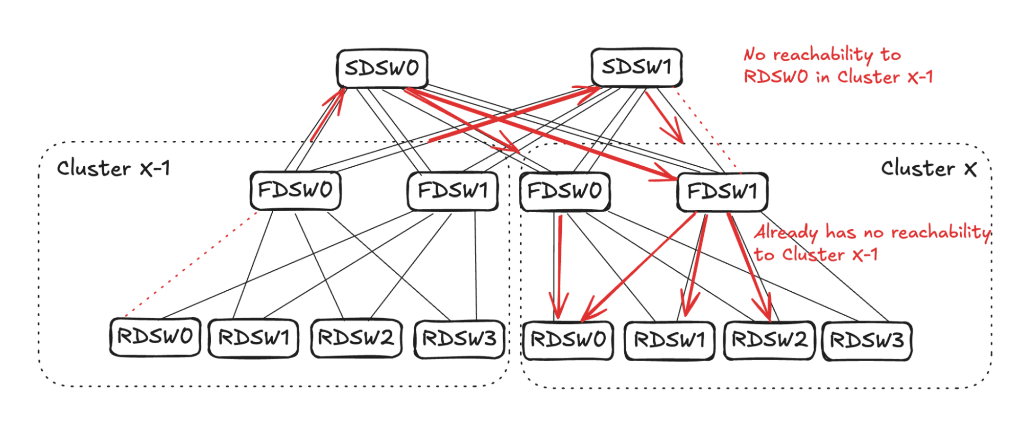
FDSW<->SDSW and RDSW<->FDSW Link Failure
Figure 12 illustrates another example of link failures occurring in between FDSW <-> SDSW, as well as RDSW <-> FDSW. The reduced reachability will propagate and then converge in both directions.
- FDSW<->SDSW link failure.
- RDSW<->FDSW link failure.
FDSW Propagation for FDSW<->SDSW Link Failure
Similar to the above FDSW propagation, FDSW1 in cluster X will randomly pick one connecting RDSW and advertise no reachability to devices towards Cluster X-1. (See Figure 13 below)
SDSW propagation for FDSW<->SDSW Link Failure
Similar to the SDSW propagation above, SDSW1 will randomly pick one link towards cluster X-1 and propagate no reachability to Cluster X. Imagine SDSW1 picks one of the links connecting FDSW0 in cluster X-1.
Note in Figure 14 that FDSW0 in Cluster X-1 already has one link failure connecting RDSW0. The input and output capacity towards Cluster X is already balanced on FDSW0, thus finishing propagation in this direction.
FDSW Propagation for RDSW<->FDSW Link Failure
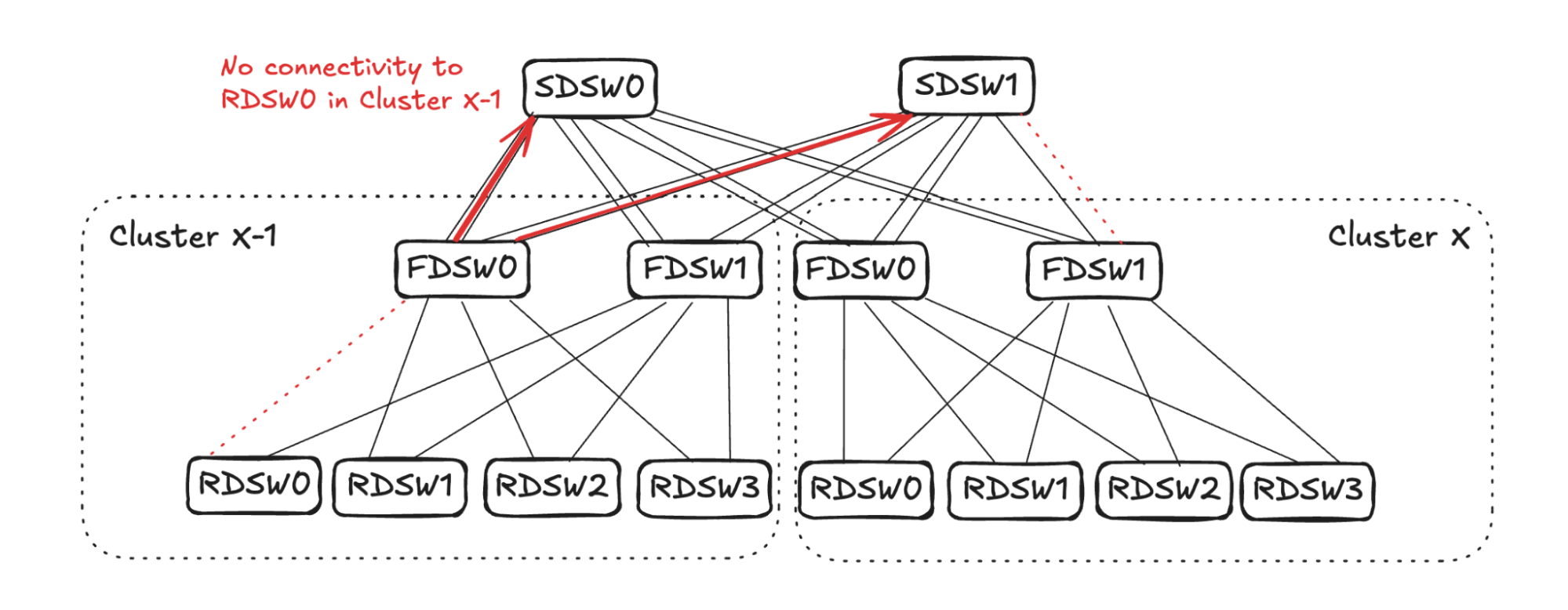
As FDSW0 in Cluster X-1 loses connectivity to RDSW0, it will stop advertising reachability to SDSW0 and SDSW1 on both of the links. (See Figure 15.)
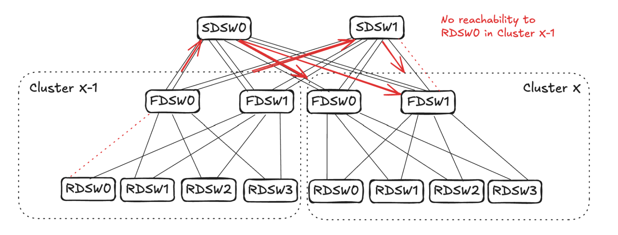
SDSW0 will randomly pick two links to stop advertising reachability to RDSW0 in Cluster X-1 (in the example in Figure 16 it picks one link in FDSW0 and one in FDSW1). On SDSW1, however, it already has one link failure connecting FDSW1 in Cluster X. Therefore, only one more link needs to be selected to propagate the reduced reachability (in the example it picks the other link towards FDSW1).
From Cluster X FDSW1’s perspective, the output capacity towards RDSW0 in Cluster X-1 is 1 (two links with no reachability, and one link failure). Therefore, to balance input it should select three links to stop advertising reachability towards RDSW0 in Cluster X-1. Note that the link FDSW1<->RDSW2 already has no reachability towards Cluster X-1 due to 1.1 propagation above. Hence, it will pick two more links (RDSW0 and RDSW1 in Figure 17) to not advertise reachability.
For Cluster X FDSW0, it will randomly pick one downlink (RDSW0 in Figure 17) to not advertise reachability to RDSW0 in Cluster X-1.
Future Work With DSF
- We are interconnecting multiple regions to create mega clusters that will provide interconnectivity of GPUs with different regions that are tens of kilometers apart.
- This will create an interesting challenge of addressing heterogeneity between different GPU types and fabric involving different regions.
- We are also working on a new technology called Hyperports, which will combine multiple 800G ports at ASIC level to act as a single physical port. This will reduce the effect of fat flows on IP interconnects.
In addition, DSF is a smart fabric that inherently supports a wide range of GPUs/NICs. We are increasing our deployments to include an increasing variety of GPU/NIC models.


