- AI networks play an important role in interconnecting tens of thousands of GPUs together, forming the foundational infrastructure for training, enabling large models with hundreds of billions of parameters such as LLAMA 3.1 405B.
- This week at ACM SIGCOMM 2024 in Sydney, Australia, we are sharing details on the network we have built at Meta over the past few years to support our large-scale distributed AI training workload.
- Our paper, “RDMA over Ethernet for Distributed AI Training at Meta Scale,” provides the details on how we design, implement, and operate one of the world’s largest AI networks at scale.
The growing prevalence of AI has introduced a new era of communication demands. Distributed training, in particular, imposes the most significant strain on data center networking infrastructure. For instance, a typical generative AI (GenAI) job may necessitate tight coordination of tens of thousands of GPUs over the course of several weeks. Constructing a reliable, high-performance network infrastructure capable of accommodating this burgeoning demand necessitates a reevaluation of data center network design.
When Meta introduced distributed GPU-based training, we decided to construct specialized data center networks tailored for these GPU clusters. We opted for RDMA Over Converged Ethernet version 2 (RoCEv2) as the inter-node communication transport for the majority of our AI capacity.
We have successfully expanded our RoCE networks, evolving from prototypes to the deployment of numerous clusters, each accommodating thousands of GPUs. These RoCE clusters support an extensive range of production distributed GPU training jobs, including ranking, content recommendation, content understanding, natural language processing, and GenAI model training, among other workloads.
Topology
We built a dedicated backend network specifically for distributed training. This allowed us to evolve, operate, and scale independently from the rest of the data center network. To support large language models (LLMs), we expanded the backend network towards the DC-scale, e.g., incorporating topology-awareness into the training job scheduler.
The separation
The training cluster relies on two independent networks: the frontend (FE) network for tasks such as data ingestion, checkpointing, and logging, and the backend (BE) network for training, as depicted below.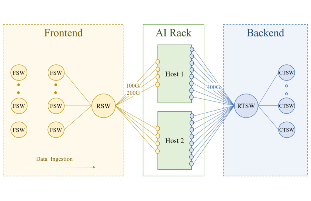
A training rack is connected to both the FE and BE of the data center network. The FE has a hierarchy of network layers – rack switches (RSWs), fabric switches (FSWs), and higher – that houses the storage warehouse, which provides GPUs with the necessary input data for training workloads. We ensure that there is enough ingress bandwidth on the rack switch to not hinder the training workload.
The BE is a specialized fabric that connects all RDMA NICs in a non-blocking architecture, providing high bandwidth, low latency, and lossless transport between any two GPUs in the cluster, regardless of their physical location. This backend fabric utilizes the RoCEv2 protocol, which encapsulates the RDMA service in UDP packets for transport over the network.
AI Zone
Our BE networks have undergone several transformations. Initially, our GPU clusters used a simple star topology with a few AI racks connected to a central Ethernet switch running the non-routable RoCEv1 protocol. This setup had clear limitations in GPU scale and switch redundancy. Therefore, we swiftly transitioned to a fabric-based architecture for extended scalability and higher availability.
We designed a two-stage Clos topology for AI racks, known as an AI Zone. The rack training switch (RTSW), serving as the leaf switch, offers scale-up connectivity for GPUs within the rack using copper-based DAC cables. The spine tier, composed of modular cluster training switches (CTSW), provides scale-out connectivity among all racks in the cluster. The CTSW has deep buffers statically divided over the ports in the chassis. The RTSWs connect to CTSWs via single-mode fiber and 400G pluggable transceivers.
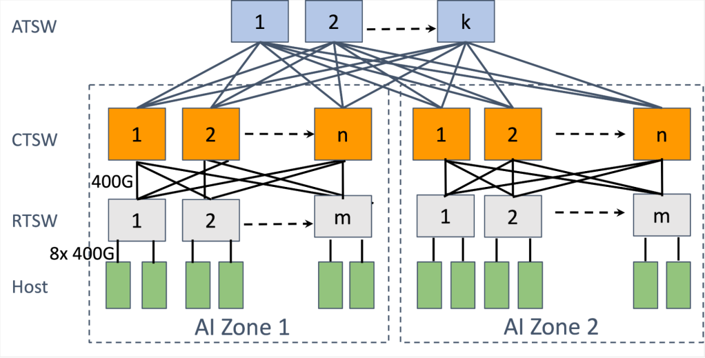
The AI Zones are designed to support a large number of interconnected GPUs in a non-blocking manner. However, emerging AI advancements, such as LLMs like Llama, demand a GPU scale larger than what a single AI zone provides. To accommodate this, we designed an aggregator training switch (ATSW) layer that connects the CTSWs in a data center building, expanding the RoCE domain beyond a single AI Zone.
Note, the cross-AI Zone connectivity is oversubscribed by design, with network traffic balanced using ECMP. To mitigate the performance bottleneck for cross-AI Zone traffic, we enhanced the training job scheduler to find a “minimum cut” when dividing the training nodes into different AI Zones, reducing the cross-AI Zone traffic and thus collective completion time. The scheduler does this by learning the position of GPU servers in the logical topology to recommend a rank assignment.
Routing
The scaling of compute power and network topology discussed above led to the question of how to efficiently balance and route the massive training traffic. Specifically, the AI training workloads had several challenging characteristics:
- Low entropy: Compared to traditional data center workloads, the number and the diversity of flows for AI workloads are much smaller and the flow patterns are usually repetitive and predictable.
- Burstiness: On the time dimension, the flows usually exhibit the “on and of”’ nature in the time granularity of milliseconds.
- Elephant flows: For each burst, the intensity of each flow could reach up to the line rate of NICs.
ECMP and path pinning
We initially considered the widely adopted ECMP, which places flows randomly based on the hashes on the five-tuple: source and destination IPs, source and destination UDP ports, and protocol. However, and as expected, ECMP rendered poor performance for the training workload due to the low flow entropy.
Alternatively, we designed and deployed a path-pinning scheme in the initial years of our deployment. This scheme routed packets to specific paths based on the destination “slice” (the index of the RTSW downlink). This worked well if each rack was fully assigned to the same job and there was no failure in the network. However, this was seldom true. We saw that the rack can be partially allocated to a job, with only one of the two hosts in the rack using the uplink bandwidth. This fragmented job placement caused uneven traffic distribution and congestion on the uplinks of the particular RTSW and degraded the training performance up to more than 30%. Further, network failures on a uplink or a CTSW caused the affected flows to be unevenly reassigned to other CTSWs by ECMP. Those reassigned flows collided with other existing flows and slowed down the whole training job.
We mitigated the immediate impact of these flow collisions by upgrading the bandwidth of the RTSW uplinks bandwidth by 2x. Hence we allowed for the RTSW uplink capacity to be 1:2 under-subscribed compared to the RTSW downlink capacity. While this mitigated the immediate performance impact, this was an expensive solution as it required 2x network capacity. Thus, we recognized this as a short-term mitigation and proceeded to further stages of routing evolution.
Queue pair scaling
We next revisited ECMP with an intent to increase the number of flows for hierarchical collectives through the queue pair (QP) scaling software feature in the collective library.
To account for this, we configured switches to perform Enhanced ECMP (E-ECMP) to additionally hash on the destination QP field of a RoCE packet using the UDF capability of the switch ASIC. This increased entropy and, compared to baseline ECMP without QP scaling, we observed that E-ECMP along with QP scaling showed performance improvement of up to 40% for the AllReduce collective.
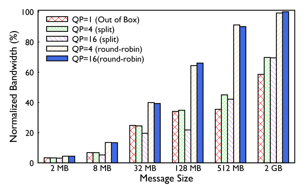
We evaluated two QP scaling strategies. The first involved splitting each message meant to be posted over a single QP, instead onto multiple QPs resulting in multiple flows. But it also produced smaller message sizes on fabric as well as multiple ACKs. The second approach involved posting each message to a different queue, in a round-robin fashion. For the NIC message sizes demonstrated in our production with NCCL, we observed the latter to be performing well. This feature has been important for ECMP scalability by increasing the network flows for hierarchical collectives like AllReduce.
While we improved ECMP performance with QP scaling, the underlying probabilistic nature of hashing was a persistent downside of this routing scheme. Also, the need to customize the QP scaling factor and methodology based on the workload type, while workable in the short-term, presented long-term operational complexity.
Congestion control
As we transitioned to 400G deployments, we attempted to tune DCQCN to adapt to new network speeds and topology. However, with default DCQCN settings and doubled ECN thresholds compared to 200G networks, performance was degraded. Further investigation revealed that DCQCN implementation in firmware has changed, introducing bugs and reduced visibility with problems relating to correct CNP counting.
We proceeded without DCQCN for our 400G deployments. At this time, we have had over a year of experience with just PFC for flow control, without any other transport-level congestion control. We have observed stable performance and lack of persistent congestion for training collectives.
Receiver-driven traffic admission
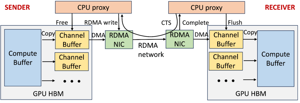
To mitigate the congestion for 400G and beyond, we co-designed the collective library and RoCE transport to enforce receiver-driven traffic admission for better performance. The diagram below shows that the GPU-to-GPU communication architecture in our production training clusters predominantly uses two-stage copy and receiver-initiated communication via the NCCL collective library. Each GPU’s high bandwidth memory (HBM) maintains multiple channels for parallel transmission of chunked collective messages. The sender GPU threads first copy data from the compute buffer to an available channel buffer. The sender CPU proxy thread can only post an RDMA write request after receiving a clear-to-send (CTS) packet from the receiver, which includes the size and memory information. The receiver’s GPU threads then copy the channel buffer contents to the destination compute buffer. Finally, CPU proxy threads on both sides recycle the channel buffer, and the receiver CPU proxy sends another CTS packet once the channel buffer is ready.
We effectively leverage this mechanism as a receiver-driven traffic admission to limit the amount of in-flight traffic on the network, especially when congestion starts to build up. However, configuring the right setting can be challenging as:
- The number of channels is limited due to the resource contention on GPU threads with concurrent compute operations;
- Setting the channel buffer size requires a more careful balance between congestion spreading and bandwidth under-utilization than Infiniband due to RoCE’s more coarse-grained flow control and possible end-host slowness.
Thus, we took two steps to improve the performance. First, we experimentally determined the right parameter settings for the number of channels and channel buffer size across various training job sizes and collective types. Second, we implemented high priority queuing at switches for CTS packets to expedite the notifications and mitigate potential bandwidth starvation.
Congestion control has been a focal point of research in RDMA networks. DCQCN has been the gold standard for storage-focused networks. However, our experience with distributed AI training workloads provides a different perspective on tailoring the congestion control algorithms. Despite turning off DCQCN and multiple instances of RTSW sending PFC to a deep-buffer CTSW, we have not encountered a scenario over the last four years where production AI training traffic causes the CTSW to send PFCs to RTSWs persistently.
Our current solution depends on careful coordination between the collective communication library and the network. It may depend on the relative throughput between GPU and network, which may not be applicable to all scenarios. We encourage the research community to put more focus on this topic.
Moving forward
The design and operation of large-scale RoCE networks for distributed AI training workloads have evolved to meet the increasing demands of computational density and scale. By segregating FE and BE networks, employing various routing schemes, and optimizing collective traffic patterns, we have been able to build a performant and reliable network infrastructure. These designs and insights underline the importance of deeply understanding the training workload and translating these implications into network component design, ultimately contributing to the advancement of distributed AI training infrastructure.
With the fast growing trend of GenAI workload, our network infrastructure will evolve rapidly.
Read the paper
RDMA over Ethernet for Distributed AI Training at Meta Scale
Acknowledgements
We would like to thank all contributors to the paper, including Rui Miao, Shengbao Zheng, Sai Jayesh Bondu, Guilherme Goes, Hany Morsy, Rohit Puri, Adi Mohammad Riftadi, Ashmitha Jeevaraj Shetty, Jingyi Yang, Shuqiang Zhang, Mikel Jimenez Fernandez, Shashi Gandham, Omar Baldonado. Many current and former people in the Network Infrastructure team at Meta have contributed to productionizing RoCE networks for AI training over the years. In particular, we would like to acknowledge Srinivas Sridharan, Petr Lapukhov, Jose Leitao, and Brandon Taylor. This work is a close collaboration with our partners in Meta’s AI Production Engineering, AI and Systems Co-design, and AI Hardware Systems teams.