
Artificial intelligence applications are rapidly evolving and increasing the demands on hardware systems. To keep up with those demands, our industry is producing new types of accelerators for machine learning, deep learning, and high-performance computing for various types of hardware — GPUs, FPGAs, ASICs, IPU, NPUs, xPUs, and the list goes on. These are generally add-in cards or accelerator modules installed on an existing system. The add-ins come in different shapes, with a range of thermal characteristics, a variety of board wiring schemes, and, in some cases, unique sockets. This leads to many form factors that are not quite the same, and whole systems that get created to accommodate one or only a few add-ins. We want systems that can accommodate many varieties of accelerators, with minimal to no redesign.
At a certain level, many of these accelerators have similar design requirements and specifications. For instance, they all require inter-module communication (to scale up) and high input/output bandwidth (to scale out). What’s needed is a common form factor so they can be used in the same system to leverage resources. To enable flexible high-speed interconnect topologies for multi-ASIC solutions, we are proposing a common form factor specification that can be used in different types of hardware accelerators.
Developing a common form factor
Various implementations have adopted available industry-standard form factors, such as PCIe CEM (the typical PCIe card form factor), as a way to reduce the time and effort required to produce a suitable solution. However, the resulting form factors are not optimized for new and evolving AI workloads, which require greater bandwidth and interconnect flexibility for data and model parallelism. For instance, state-of-the-art applications require multiple cards in a system, with multiple inter-card links running at high bandwidth. Using PCIe CEM for these poses several challenges. You’d need additional high-speed connectors and cables (or PCBA) for inter-card connection, which would reduce robustness and serviceability and limit the supported inter-card topologies. Furthermore, you’d experience excessive insertion loss from ASIC to interconnect connectors, as well as reduced power scalability. Cables can (and often do) create airflow and thermal challenges, and many accelerators already have very high thermal output. This makes the tough challenge of cooling even tougher. We need a more optimized solution.
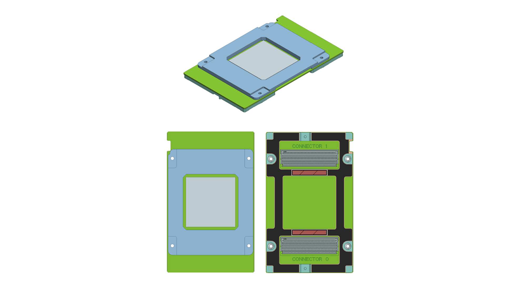
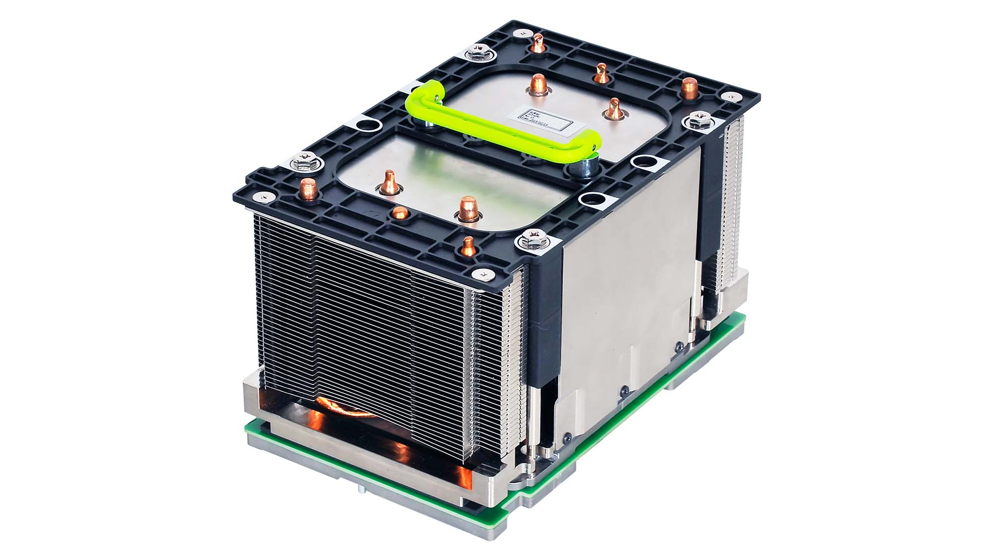
We worked with partners within the Open Compute Project (OCP) community and developed mezzanine-based OCP Accelerator Modules (OAM) as a common form factor that different types of hardware accelerator solutions can follow.
The high-level spec of the OAM includes:
- Support for both 12V and 48V as input
- Up to 350W (12V) and up to 700w (48V) TDP
- Dimensions of 102mm x 165mm
- Support for single or multiple ASICs per module
- Up to eight x16 links (host + inter-module links)
- Support for one or two x16 high-speed links to host
- Up to seven x16 high-speed interconnect links
- Expect to support up to 450W (air-cooled) and 700W (liquid-cooled)
- System management and debug interfaces
- Up to eight accelerator modules per system
With 102mm x 165mm OAM dimensions, a 416mm-wide baseboard with up to eight OAMs could fit in a blade/chassis in a 19-inch rack. The OAM links support bifurcation for different numbers of interconnect links and different number of lanes per link.
The OAM spec defines both 12V and 48V input pins to support low-TDP and high-TDP accelerator modules. For even higher-power modules, it is possible to further bypass 12V to provide more 48V capacity, but in that particular case, the modules or baseboards won’t be mixed-use.
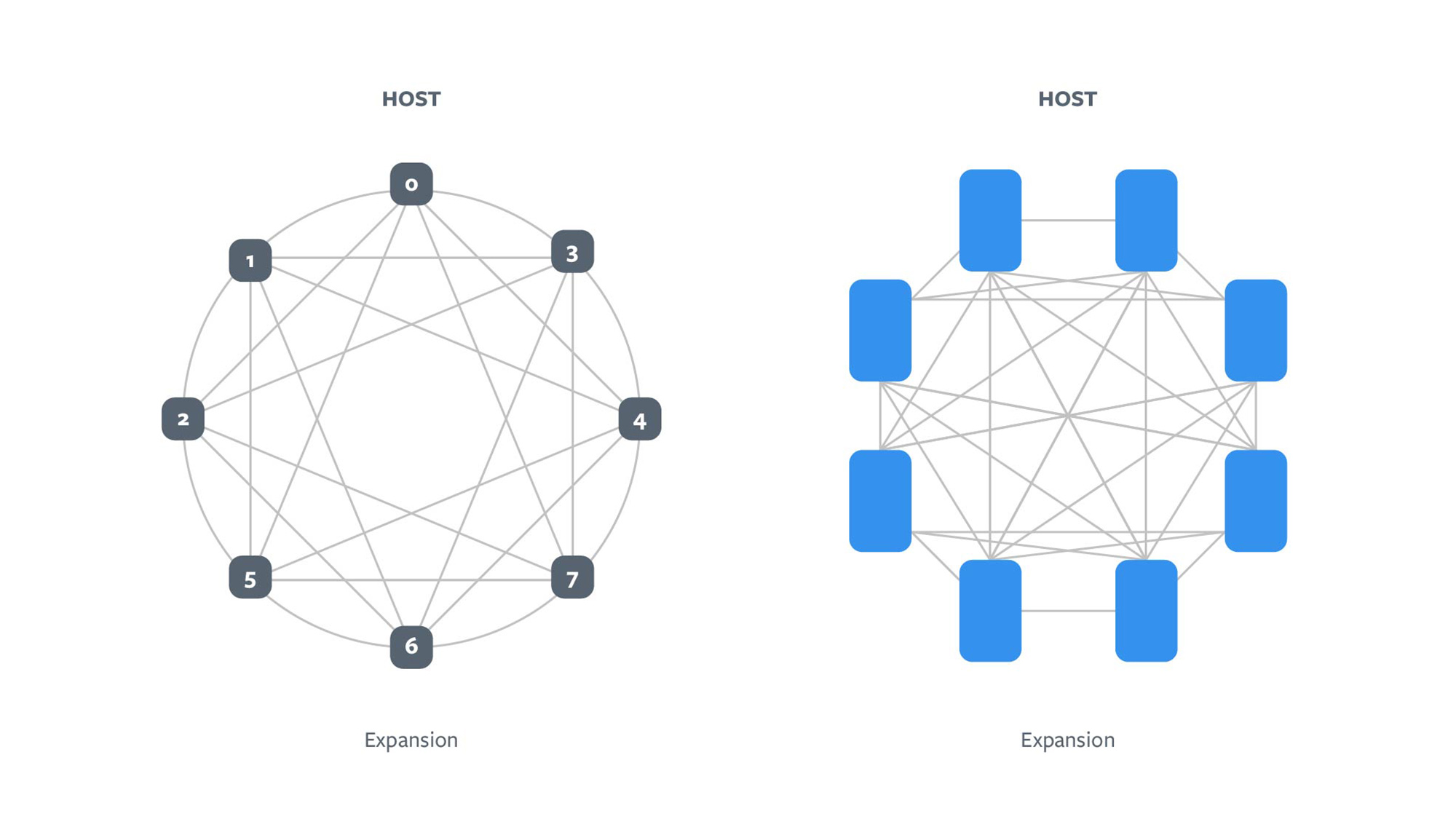
Different neural networks benefit from different interconnect topologies. The spec defines several interconnect topologies, including hybrid cube mesh (HCM) and fully connected (FC). Here are baseboard topology examples:
INTERCONNECT TOPOLOGY EXAMPLES
Looking ahead
Based on this OAM specification, various design and product implementations may maintain interoperability while offering enhancements in each hierarchy level.
We have contributed this design specification to the OCP community. OCP Server Project has formed the OAM subgroup to further develop the universal baseboard (UBB) supporting various interconnect topologies, Tray for sliding a collection of OAMs (different UBBs), and system chassis. This subgroup will cover many different areas in depth including system power delivery, signal integrity, mechanical design, thermal, serviceability, rack power, rack density, and scalability, as well as the host interfaces.
The common form factor concept for the module lowers the enabling barrier to address industry needs while increasing the production volume, reliability, and robustness of OAM. We believe open collaboration helps foster innovation for future designs. With broad participation, we imagine OAM can do for accelerators what PCIe CEM has done for other devices, creating a great platform for silicon developers in a way that’s simpler and more optimized for hardware systems engineers.
The OAM specification is publicly available through OCP. We invite you to join us as we continue to develop and enhance the designs and solution sets around the OAM modules.


